


*I don't recommend this, it's been a headache doing it this way.The best way is to order new coilpack connector housings and slide the original terminals into the new housings (no crimping or soldering necessary).
Background:
Toyota's "rat-nest" style ignition setup causes extreme heat and for most of the components including wiring to become brittle, especially the coilpack connectors. The biggest issue this causes is the "connectors" (the ignition side) that go to the coilpacks basically become brittle and disintegrate. I'd say at the age of these cars/engines that you should plan to do this mod/replacement if you even consider doing the spark plugs or even just unplugging the connectors. They are almost guaranteed to become loose and cause ignition issues (you may plug it in but internally the pins will not be sitting right, this could cause random stalling or other ignition issues that are hard to trace, I've been in this bolt for months lol). I noticed this after carefully inspecting my connectors one day and ended up pulling the pins out and plugging them in directly (but this is not a permanent fix and you should really replace these connectors as shown below).
Howto:
The way I did it was to order new connectors with leads from eBay (the VVTi 2JZ-GTE only requires 3 but the non-VVTi will require all 6 since it has 6-coilpacks whereas the VVTi only has 3). Some people just buy a new housing and hookup their existing stock pins to this (I don't recommend it as others have said this could be half of the ignition troubles, the pins could be dodgy bad/bad solder etc..., so might as well replace it all to be sure).
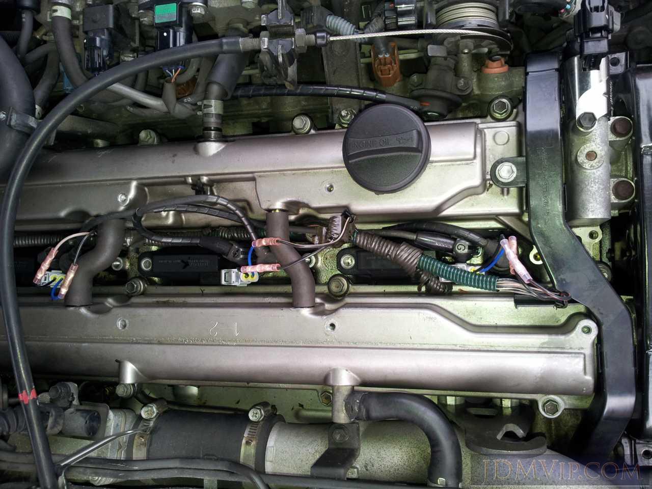
1.) Crimp butt connectors onto them (soldering is OK too but I thought it would be too difficult to solder on top of the engine).
Be very careful not to pull on the wires when crimping as one of my wires came loose from the pin. The only way to fix it is to use needle nose pliers or to remove the actual pin from the housing and solder it (really this should have been done already from the eBay seller).
2.) Crimp to engine side
Here is my method, I was paranoid about messing with the wiring or causing a no-start condition so here's my "fool-proof" method.
1.) Take a clear pic of the wiring going into each connector just in case so there's no guessing in case you make a wiring mistake.
2.) Start from the front connector.
3.) When doing the connector pick the same wire to clip/crimp first (I always chose the bottom).
4.) If your stock connector is still plugged in/alive then disconnect it.
*If it is just plugged in by individual wires then don't remove it until you clip one of the pins off (to avoid mixing up positive/negative).
5.) Clip off the "bottom" pin from the stock connector.
6.) Plugin the new connector (this way you can't mix up the orientation of top/bottom wire).
7.) Crimp the bottom wire from the new connector to the bottom wire from the stock pin.
8.) Clip the top pin from the old connector and crimp it into the top butt connector of the new wiring.
9.) Make sure the engine turns on and runs properly before moving on to the next connector.
10.) Make sure your coil packs and plugs are seated properly after crimping.
*One thing to note is if your situation is like mine (your car has the coilpacks not bolted in due to other maintenance) that you may think you've caused a wiring issue when it's just that the stock coilpacks are very sensitive to the point that plugging in a new connector will cause them to shift and misfire to the point the engine dies/idles rough/RPMs drop. Usually pressing firmly on the coilpack and making sure it's seated/sitting properly will confirm this.
I hope this helps some people and saves time/hassle/headache. This is all well and simple but all the ignition Q&As I've learned aren't obvious at first. If I've missed anything or someone has more info/better ways of doing it then please let us know in this thread.


 Reply With Quote